CNC Surface Milling
CNC surface milling with RhinoCAM
Contents
- CNC Surface Milling
- Machine Setup
- Stock
- Tools
- Machining Operations
- Simulation
- Machining
- Thermoforming
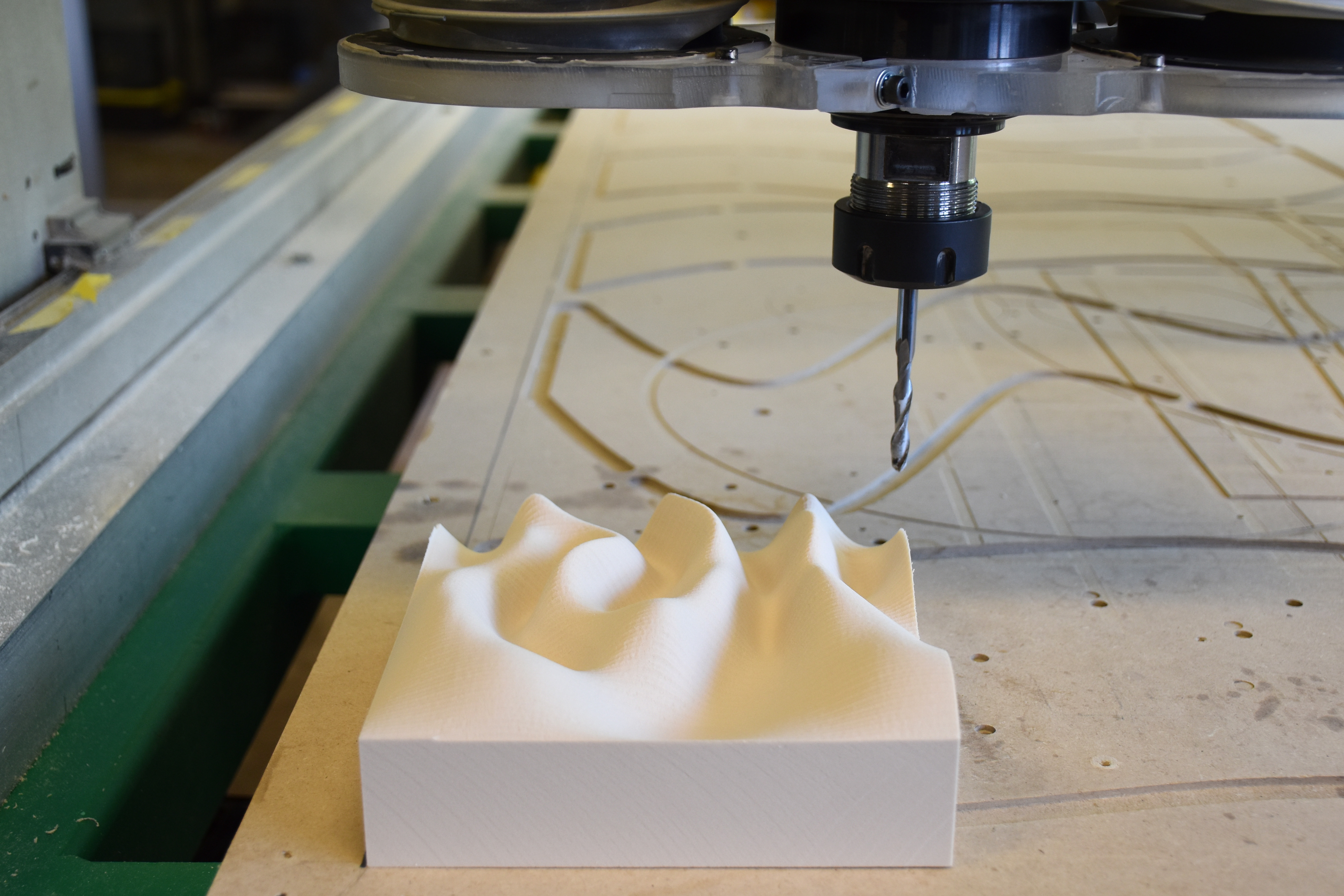
CNC Surface Milling
Use computer numerical controlled (CNC) milling
to digitally fabricate a topographic model
in Rhino with the
RhinoCAM plugin.
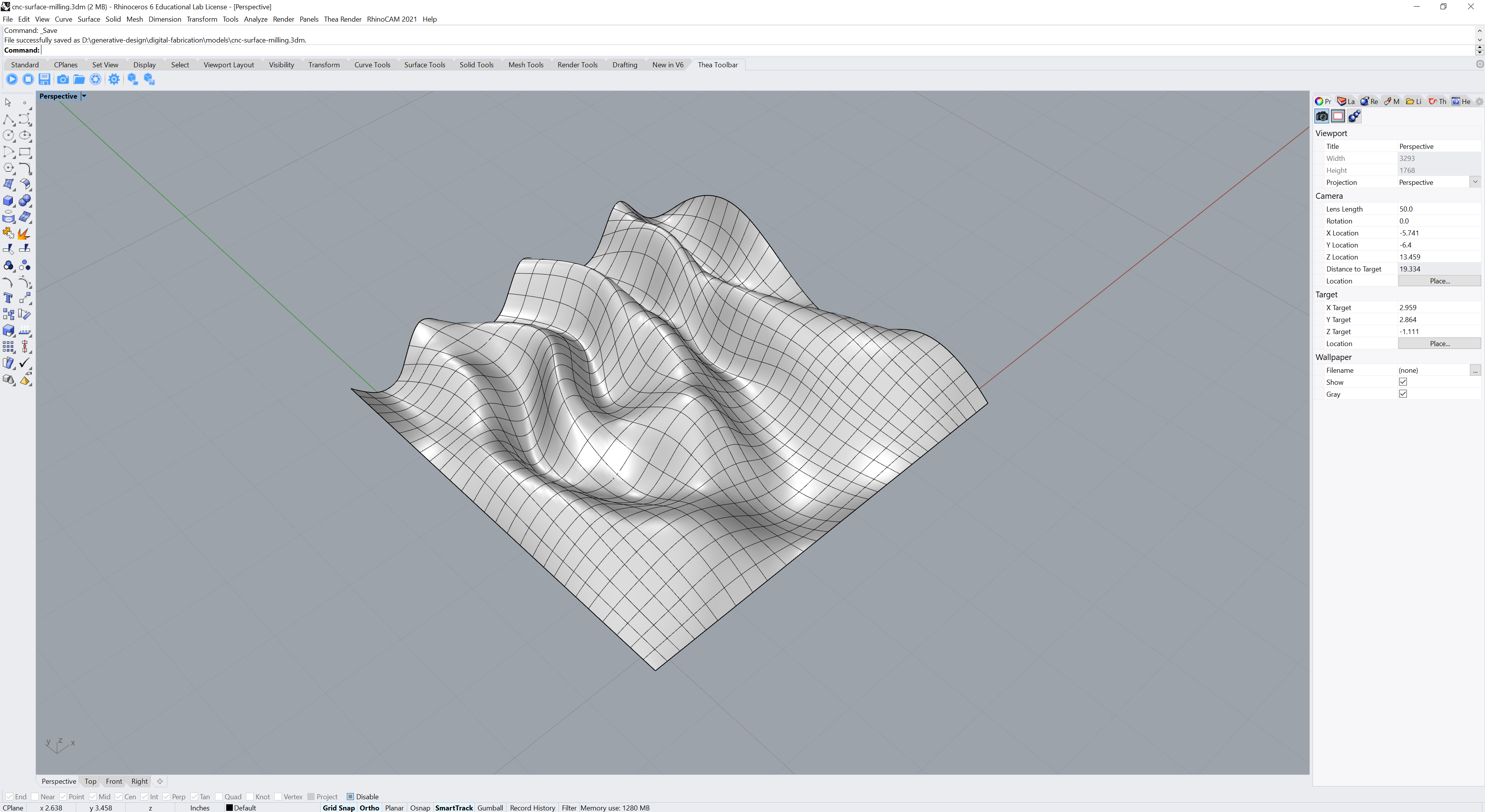
Download the Rhino model
for this tutorial.
This model was generated by the Grasshopper definition
trigonometric-landforms.gh.
This tutorial is written for a 3-axis
Forest Scientific CNC Router
using VelocityCNCmill as the post processor.
Watch at
or
.
Machine Setup
Start Rhino and set the units to Inches.
In the RhinoCAM menu switch to the MILL module for CNC milling.
In RhinoCAM’s Machining Browser in the Program tab
use the default 3 Axis machine.
In Post set the post processor to VelocityCNCmill.
Set the posted file extension to a .nc numeric control file.
Stock
The stock for this CNC milling exercise is a 6” x 6” x 2” block of high-density urethane (HDU) foam board such as Renshape or Signfoam.
In RhinoCAM’s Machining Browser in the Program tab
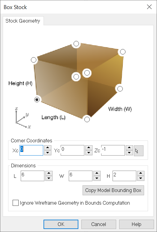
in Stock select Box Stock
and set the dimensions to 6” long, 6” wide, and 2” high.
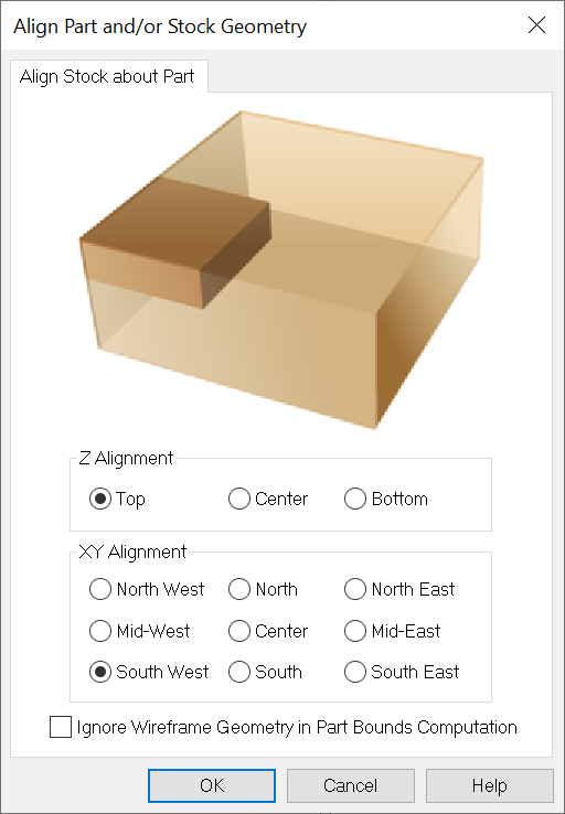
In Align select Align Stock
and set Z alignment to Top
and XY alignment to South West.
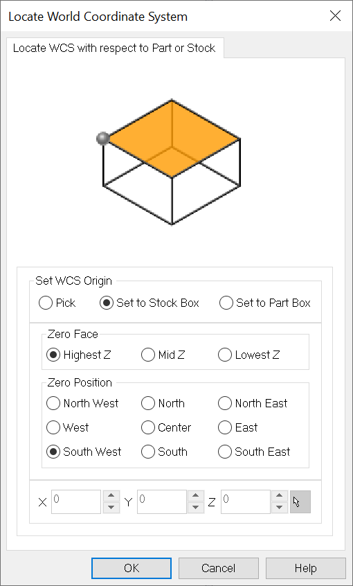
Then in In Align select Set World C.S.
and set the origin to the stock box,
set the zero face to Highest Z,
and the zero position to South West.
Tools
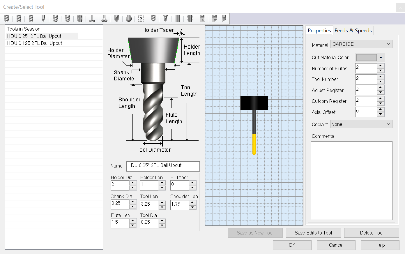
In the Machining Objects panel create a new tool.
This will be a ball end mill made of carbide
with a 0.25” diameter and 2 flutes.
The feed rate and speed depend
on the tool, stock, and machining operation.
Set the tool type to Ball Mill,
tool length to 3.25,
shoulder length to 1.75,
flute length to 1.5,
and the tool diameter to 0.25.
In the properties tab
set the material to carbide
and the number of flutes to 2.
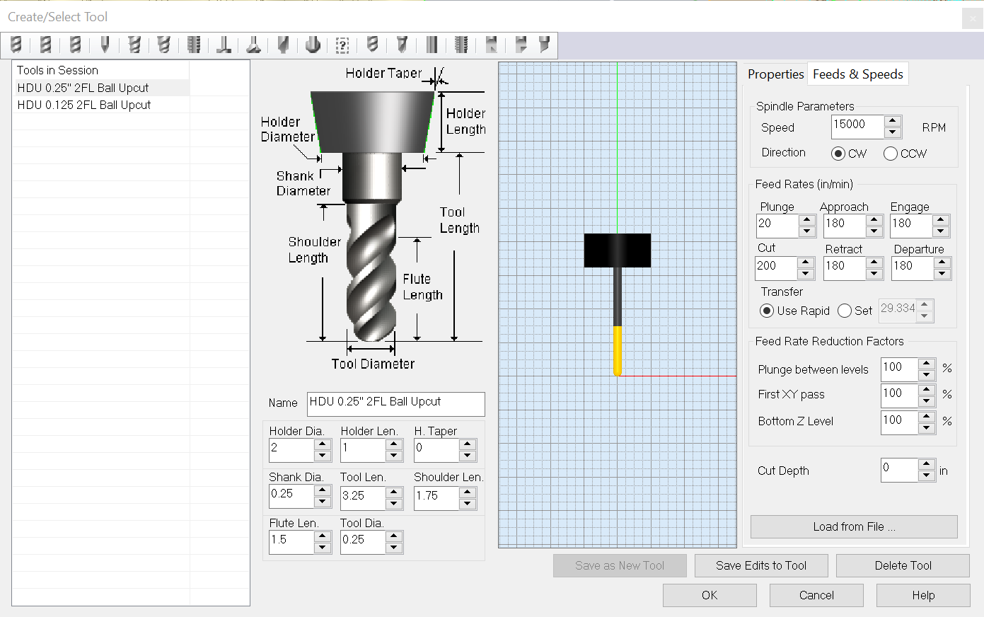
In the feeds and speeds tab
set the speed to 15000 RPM,
plunge to 20,
approach to 180,
engage to 180,
cut to 200,
retract to 180,
and departure to 180.
Save the tool.
Alternatively in the Machining Objects panel load the
cnc_surface_tools.csv
tool library.
Feeds & Speeds
| Speed | Plunge | Approach | Cut | Retract | Departure |
|---|---|---|---|---|---|
| 15000 | 20 | 180 | 200 | 180 | 180 |
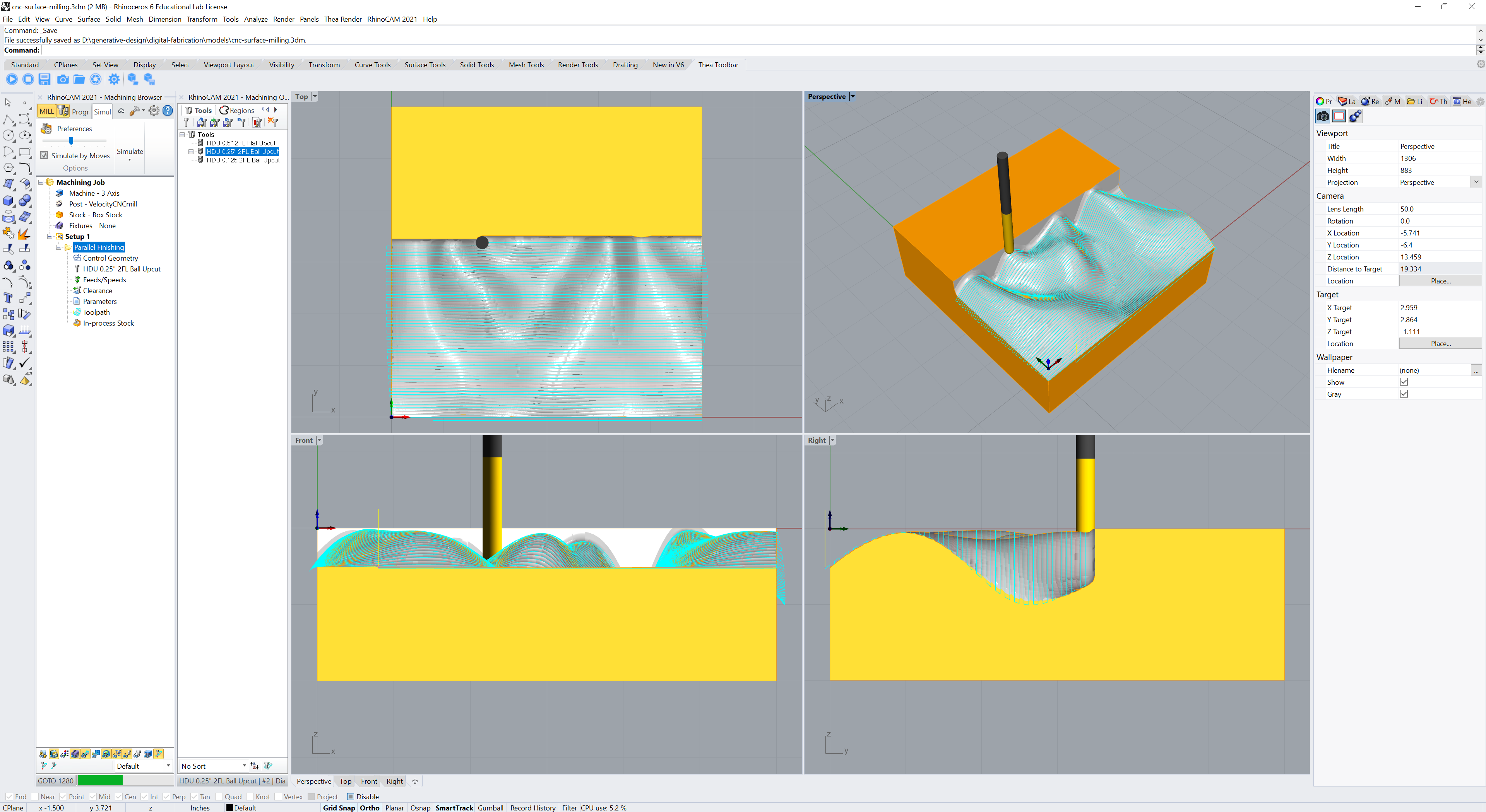
Machining Operations
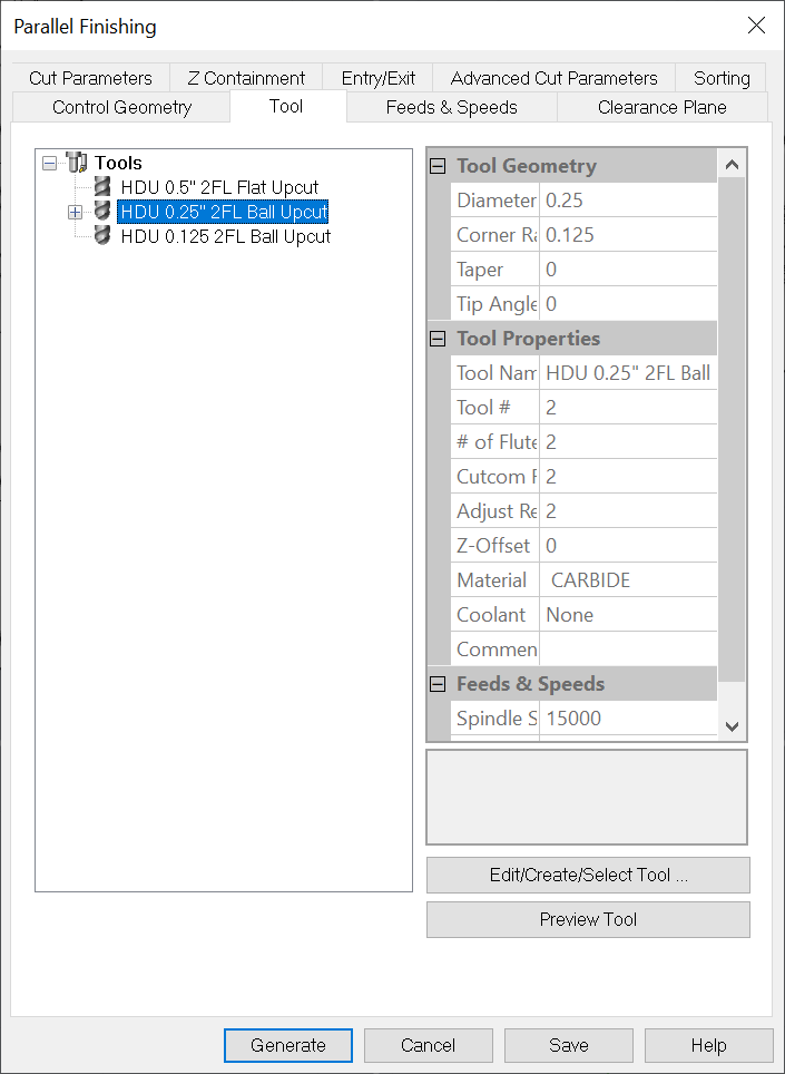
In the Machining Browser in the Program tab
in Machining Operations under
3-Axis Advanced select
Parallel Finishing.
In the tool tab select the 0.25” ball end mill.
In the feeds and speeds tab load the settings from the tool.
In cut parameters set the stepover to 25% of the tool diameter.
Generate the toolpath.
Then right click on the parallel finishing operation
and select post to export the toolpath
as a .nc numerical control file.
Save the numerical control file to a USB drive
to load onto the computer connected to the CNC machine.
Simulation
In the Simulation tab of the Machining Browser
under Simulate select Play
to simulate the machining operation in Rhino’s viewports.
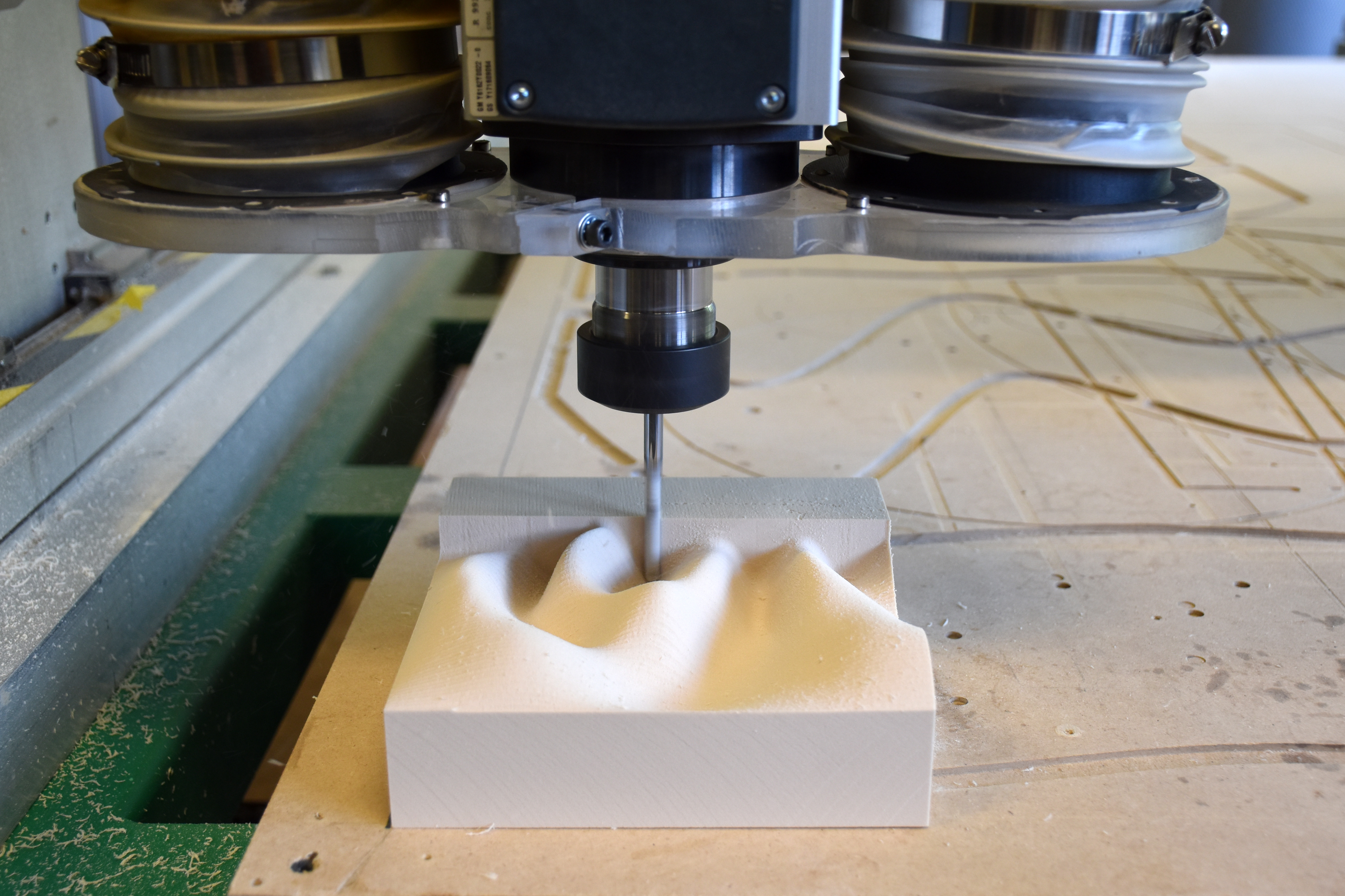
Machining
Checklist
- …
Thermoforming
Checklist
- Turn power switch on (at the back bottom)
- Set mode to
Acrylic 8and start heating - Raise bed, tape down model, and lower bed
- Open cover, place acrylic sheet, and close cover
- Pull heating element forward
- Wait 90 seconds until acrylic is hot
- Push heating element back
- Turn off vacuums
- Raise bed to form the model
- Cool model with air hose
- Puff the acrylic to release the model
- Open cover and remove model